NEMA Wiring Diagram Guide for Electrical Experts
Nearly seventy percent of electrical breakdowns across installations stem from inadequate wiring techniques. This fact accentuates the requirement of complying with set guidelines, underscoring NEMA wiring diagrams’ value for electrical specialists. By means of these drawings, wiring arrangements that satisfy both performance productivity and supreme protection standards are presented.
The objective of this guide is to provide electrical practitioners with deep insights into NEMA norms. Highlighting the significance of accurate electrical setups is vital. By learning these rules, practitioners can significantly reduce the risk of accidents and guarantee they comply with safety measures endorsed by Installation Parts Supply. Understanding of l 14-30 plug is essential whether creating modern setups or servicing current ones, as it boosts the ability to offer safe and dependable electrical solutions.
Main Points
- NEMA wiring diagrams are vital for maintaining electrical security and conformity.
- Correct wiring techniques can minimize electrical failures considerably.
- Comprehending NEMA criteria improves the effectiveness of electrical arrangements.
- Installation Parts Supply encourages following safety standards in electrical tasks.
- NEMA schematics accommodate a broad spectrum of uses across multiple industries.
Comprehending NEMA Criteria and Their Significance
NEMA criteria are essential in the electrical sector, guiding safety and operation carefully. Developed by the National Electrical Manufacturers Association, they set pivotal standards for designing, testing, and identifying electrical appliances. This ensures uniformity and trustworthiness across all electrical set-ups, which is invaluable.
Which Are NEMA Norms?
NEMA classifications span from levels 1 to 13. Every level defines the criteria necessary for electrical devices to function optimally. For instance, NEMA 1 provides basic indoor protection but does not offer dust resistance. On the other hand, NEMA 4 ensures devices is waterproof, a must for surviving significant water immersion. Understanding these classifications is key in choosing suitable equipment.
Why NEMA Norms Matter for Electrical Safety
The impact of NEMA standards in maintaining electrical protection is substantial. They contribute greatly in reducing electrocution risks, equipment malfunctions, and burn risks. Accurate adherence to NEMA classifications enables devices to function reliably under particular environmental conditions. For external deployment, NEMA 3 ratings deliver protection against the elements, guarding the apparatus from harsh conditions like rain and snowfall. In areas at risk of explosions, classifications such as NEMA 7, 8, and 9 are critical for maintaining protection.
Implementations of NEMA Criteria in Wiring Drawings
The use of NEMA criteria in wiring diagrams is crucial for protected, efficient electrical setups. These schematics utilize standardized symbols and formats originating from NEMA classifications, streamlining the comprehension of detailed electrical arrangements. Such standardization is helpful. It encourages lucidity, uniformity, and minimizes confusions, thus improving electrical protection across domestic and commercial landscapes.
NEMA Wiring Diagram Fundamentals
NEMA wiring diagrams are essential for electrical professionals, rendering intricate junctions unambiguous. They detail the linkages and elements in various setups. By grasping the parts, categories, and symbols of NEMA schematics, technicians can boost their performance in deployments and upkeep.
Elements of NEMA Wiring Diagrams
NEMA drawings comprise crucial parts for specific electrical installations. You’ll discover wiring endpoints, couplers, and other equipment for safe junctions. Every piece guarantees power is spread optimally, complying with safety guidelines.
Types of NEMA Wiring Diagrams
NEMA employs various diagrams, like connection blueprints and electrical arrangements. These schematics detail appliance associations, while designs display energy distribution. Selecting the right diagram helps with troubleshooting and deployment.
Common Notations Employed in NEMA Wiring Diagrams
Icons in wiring diagrams are vital for clear clarity. They illustrate switches, networks, and couplers. Knowing these symbols assists groups interpret drawings accurately. Thus, it guarantees configurations meet NEMA standards.
NEMA Wiring Schematic Characteristics
For electrical professionals, understanding the key elements of precise electrical wiring schematics is crucial. These drawings bring both transparency and thoroughness, matching setups with NEMA norms. They require accurate marking and scaling to minimize installation errors. This fosters a more secure and highly efficient operational setting.
Key Features of Accurate Electrical Wiring Drawings
Correct electrical wiring diagrams are essential in electrical projects. They incorporate key features such as:
- Lucidity: Diagrams should be simple, reducing the risk of misinterpretation.
- Completeness: They need to contain all vital components, linkages, and electrical ratings.
- Adherence to Standards: Adherence to NEMA criteria is imperative for ensuring security and operation.
- Detailed Labeling: Clear labels on each part are essential for understanding and avoiding mistakes.
- Accurate Proportions: The scales should replicate the true setup to depict the configuration correctly.
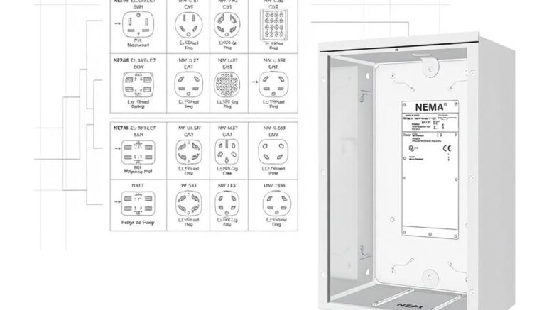
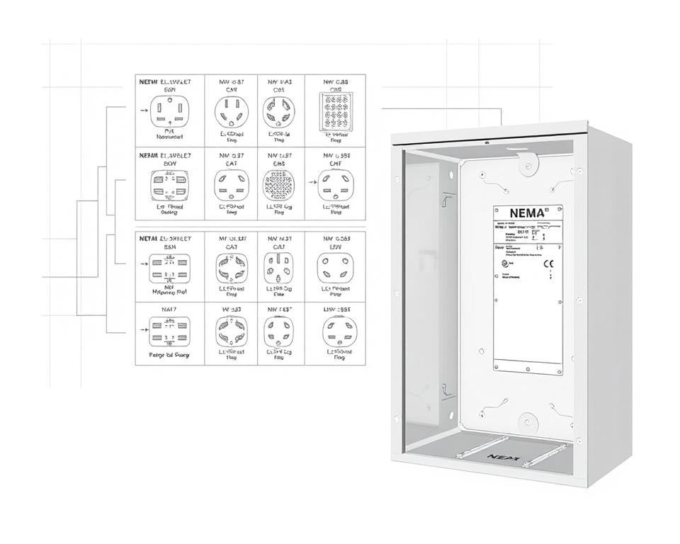
Grasping NEMA Coupler Layout
Understanding of NEMA coupler configuration is crucial for establishing proper junctions in electrical systems. Understanding of particular pin arrangements upholds protection and device operation. There exists a diversity of NEMA interfaces, crafted for specific voltage levels and flows, encompassing:
| NEMA Connector Type | Amperage Rating | Voltage Level |
|---|---|---|
| L5-15 | 15A | 125V |
| L5-20 | 20A | 125V |
| L14-20 | 20A | 125/250V |
| L1430C | 30A | 125/250V |
| L620C | 20A | 250V |
| L1430C | 30A | 125/250V |
| L630R | 30A | 250V |
Grasping NEMA coupler layouts is essential for secure connections, improving performance. It’s paramount to align connectors with equipment accurately using twist-lock or linear blade variants, to prevent safety risks.
NEMA Appliance Wiring
NEMA device wiring covers various configurations for protected electrical appliance interfaces. These standards confirm that appliances integrate securely, reducing risk. Grasping the different NEMA equipment and their wiring is essential for specialists.
Different Kinds of NEMA Devices
NEMA categorizes units by kind based on voltage levels and flow requirements. Key setups are:
- 2-Pole 2-Wire
- 2-Pole 3-Wire Grounding
- 3-Pole, 3-Wire
- 3-Pole 4-Wire Grounding
- 4-Pole, 4-Wire
- 4-Pole, 5-Wire with Grounding
These configurations are utilized in domestic settings and manufacturing plants, handling 125V, 208V, and 480V.
NEMA Plug Wiring Explained
NEMA plug wiring changes to suit multiple energy requirements, with locking types delivering consistent junctions in vibrating conditions. For instance, the L5-15 plug operates at 15 amps, typical of business sites, whereas the L14-20 is intended for 20 amperes at 125/250 voltage.
The NEMA labeling convention helps in choosing the correct plugs, highlighting features like electrical polarity and earthing. Such accuracy secures that appliances perform reliably.
NEMA Outlet Wiring Standards
Accurate wiring of NEMA sockets meets electrical standards and security protocols. For instance, L530R receptacles are rated for 30 amperes at 125 voltage, with L630R variants for 250 volts. Correct grounding is vital to avoid electrical errors.
Selecting certified NEMA plugs and receptacles guarantees safe, regulation-compliant configurations. It’s vital to refer to official guidelines when setting up.
NEMA Motor Wiring and Applications
NEMA motor wiring is essential in electrical engineering, notably for industrial use. Understanding how NEMA motor setup works ensures that engines are set up for peak efficiency. These motors, like one-phase and tri-phase types, need correct wiring to work safely and optimally.
Introduction of NEMA Motor Wiring
Grasping NEMA motor wiring requires understanding of linkages and configurations. Most three-phase motors now support dual-voltage, indicating they can operate at both low (208-230V) and high power levels (460V). Wiring at high voltage results in lower current draw than at low voltage. The benefits of high voltage include thinner cables for the power feed, a notable benefit for units over 10 HP.
While both NEMA and IEC units are employed in the sector, NEMA variants are usually larger and more costly than IEC ones for less than 100 HP deployments. NEMA controllers range from size 00 to 9, appropriate for multiple functions. A common characteristic in NEMA starters is a Trip Rating of 20, engineered to trigger when a motor’s current surpasses 6x the Full Load Amperage in 10 seconds.
Choosing the Correct NEMA Motor Configuration
Choosing the right NEMA motor configuration impacts system performance and security. A common three-wire control circuit employs three wires for a start/stop pushbutton station, allowing straightforward motor management. Typical three-phase setups consist of the 12 Lead Dual Voltage and 6 Lead, facilitating Wye and Delta configurations.
IEC motor starters often include phase failure detection, enhancing safety. They also feature configurable Trip Classes for customized protection in low power operations. Moreover, many units have thermal protection, critical for Single Phase and Dual Voltage systems.
| Arrangement | Power Type | Current Specification | Typical Use |
|---|---|---|---|
| 12 Lead Dual Voltage | Dual Voltage (208-230V / 460V) | Varies by motor size | Wye Start and Delta Run setups |
| 6 Lead | Single/Dual Voltage | Maximum 32A | Both Wye and Delta arrangements |
| Single Phase | One Voltage | Varies (1-5 amps adjustment) | Two Speed, Two Winding applications |
| Delta Connection | Elevated Voltage | Variable | Used for Current Transformers and various setups |
In Summary
Comprehending NEMA wiring drawings and norms is vital for electrical experts looking to enhance their expertise and comply with electrical security guidelines. These standards secure protected and effective electrical configurations but also avoid dangers stemming from faulty wiring. In summary, following NEMA standards leads to the enhanced functionality of multiple NEMA units and systems.
For electricians, the selection of superior supplies can greatly affect the result of their tasks. Installation Parts Supply provides a vast range of wiring supplies in accordance with NEMA norms. This empowers experts to obtain essential parts for meeting these significant standards. High-quality resources and comprehensive knowledge of NEMA wiring diagrams greatly enhance project protection and effectiveness.
During electrical deployments, always prioritize safety and precision above all. Mastering NEMA criteria delivers the insight needed for executing industry standards accurately. This guarantees that each electrical connection established aligns with superior norms.
Common Questions
Which are NEMA wiring diagrams?
NEMA wiring drawings display the arrangements and junctions of NEMA-standard electrical appliances. They comply with safety and functional standards defined by the National Electrical Manufacturers Association.
Why are NEMA norms vital for electrical protection?
NEMA standards are fundamental to defining safety and operational standards for electrical devices. These principles help electrical experts minimize electric shock, device malfunctions, and burn dangers.
Identify the key parts are crucial in a NEMA wiring schematic?
Essential components in a NEMA wiring schematic include electrical layouts and linkage diagrams. These schematics also offer thorough labels and show the electrical system’s different parts accurately for installations.
What types of NEMA wiring diagrams are used?
Diverse NEMA wiring diagrams serve diverse needs, including circuitry for power distribution and connector schematics. Each layout plays a unique role in electrical systems.
Which are the typical symbols employed in NEMA wiring diagrams?
Common symbols in these diagrams represent switches, fuses, sockets, and more. Use of these symbols promotes unambiguous conveyance and precise understanding of wiring diagrams.
What are the essential attributes of precise electrical wiring diagrams?
Precision in electrical wiring diagrams is defined by their clarity, thoroughness, and detailed labeling. They must align with NEMA criteria to avert faults in installation.
Explain a NEMA connector configuration?
A NEMA connector pinout describes electrical junctions at a connector, showing distinct pin functions. This secures reliable and effective linkages in electrical networks.
Identify the different kinds of NEMA devices?
NEMA devices include various electrical receptacles and couplers, like adapters and outlets. They are engineered for diverse current and voltage specifications to meet unique application requirements.
In what way is NEMA plug wiring set up?
NEMA plug wiring is determined by specific amperage and voltage needs, adhering to security protocols and electrical codes for various electrical uses.
What guidelines are there for NEMA outlet wiring?
Standards for connecting NEMA sockets underline following electrical regulations, guaranteeing proper electrical polarity, and choosing appropriate wire sizes. This maintains both protection and performance in electrical setups.
How can I wire a NEMA motor effectively?
To connect a NEMA motor, one must comprehend its specific one-phase or three-phase arrangement. Selecting the correct wiring technique is crucial, along with maintaining electrical security for enhanced motor functionality.
Which factors should be considered when selecting a NEMA motor configuration?
Opting for a NEMA motor arrangement necessitates an analysis of the system’s power needs and performance traits. It’s also crucial to verify suitability with pre-existing equipment for guaranteed performance and security.